PLATE STRIPPING TUTORIAL (Old Method)
SmartCluster now provides a more automated way of doing this. See SmartCluster: Strip Cut.
This example shows how to cut a set of long rectangular strips using multiple torches (plate stripping).
In this example we want to strip a 2400×6000 plate into 6 350×5500 strips using the gas torch.
STEP 1: CREATE A WORKORDER WITH THE REQUESTED RECTANGLES TO BE STRIPPED
Just use a standard rectangular shape to define the geometry for the strips as above.
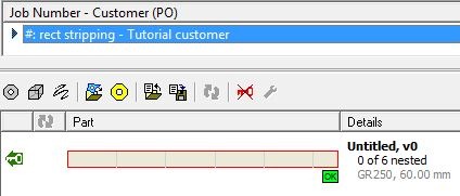
STEP 2: NEST THE STRIPS AS AN ARRAY ON A SUITABLE PLATE
- Right click on the workorder, open the parts in Nesting Mode.
- Open a suitable plate (2400×6000 of similar material), or create one if needed.
- Drag the rectangle onto the plate and place it at the bottom left
- Drag the array handle so an array of 6 plates is created:
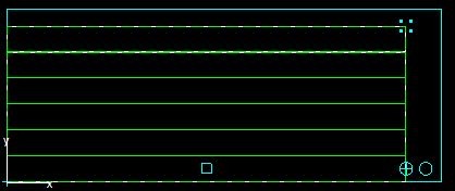
- Right Click and choose Create and Edit Cluster
STEP 3: CREATE THE COMMON LINE CUT PATHS AND SPLIT IT UP THE CUTS
We will assume for simplicity that the kerf offset for the flame torch we are using is 1mm (ie total width of the cut is 2mm). Use the common line cutting wizard to join the rectangles together, using the start pont as the anchor point. Refer to the common line cutting tutorial in the Tutorials Manual if you are unsure of how to do this.
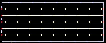
Explode the outer path, as we will want to cut its two long horzontal edges in the stripping pass also.
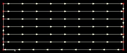
Note Carefully: The bottom path is in the wrong direction, and also has kerf left applied. the topmost cut is in the right drection, but also is intended to be cut “kerf left”, while the internal common cuts are intended to be cut with no kerf. As a result, if we measure between these paths we will find that the distance between any two common cuts is 352mm (350+ twice the kerf offset), BUT the distance between the top and bottom cuts is just 351mm (350+ a single kerf offset). Why? Because the common lines were created for a simple common line cut, and if the outside path is cut in the direction indicated with a kerf left offset at the machine of 1mm, all the strips will be the same width.
To correct this (optional, as below we will only cut the bottom path) we should offset the top and bottom paths by 1mm also (then reverse the bottom path). We could leave the end cuts as is, so long as we cut them with Kerf Left, but it may be easier to cut everything with no kerf to avoid confusion, so we will offset all 4 external cuts, removing the original entities:
STEP 4: PROCESS IT AND SETUP THE MULTICUT
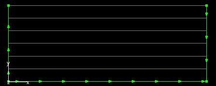
In actual fact all we really need is the two ends and the bottom cut.
Select these and process them with the Oxy Cutting Tool- in our example we have an 8 torch machine so the box count for the oxy cut tool is set to 8 in our Machines section. This program will use 7 of them.
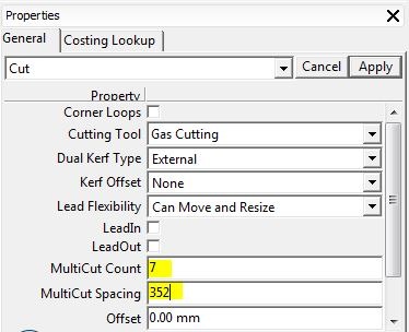
Select just the bottom cut and set its MultiCut count to 7, and its multiCut Spacing to 352 (350mm + twice the kerf offset):
The multicut processing is done:

STEP 5: CHECK THE SEQUENCE
For stripping we will usually want the long multitorch stripping performed first, so in the sequencing editor ensure it is cut before the end cuts:
