Common Line Cutting
Common Line Cutting is a way of creating SmartClusters. It creates clusters by making a shared line between parts.
The use of the shared cut line may reduce plate waste and shorten total cut length and thus time. It may however compromise part quality; especially with processes like plasma where there is a “good” side and a “scrap” side to the cut. It is important that Primecut has correct kerf data, or that the operator knows and enters the kerf, as common line cutting involves Primecut explicitly offsetting the geometry based on kerf. This makes kerf adjustment at the machine impossible.
Creating a SmartCluster for Common Line Cutting
In nesting mode you select a group of parts you want to common line. The selection can be a row, a column, or an array of parts. The parts will often be identical but a selection of dissimilar parts may also be used:
The Create SmartCluster window can be opened by using the ‘S’ key or right-clicking and selecting the SmartCluster option once you have selected your parts.
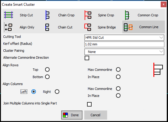
Tool and Kerf Offset
Select your cutting tool in the Cutting Tool dropdown box. (If the part was already processed with a cutting tool, the same cutting tool will be populated for you) The kerf offset should automatically be filled in from the selected tool, but can be changed if you want. Once it has been changed, in order to get back to the default value, simply select a tool from the drop-down menu, or re-select the same tool. The common line cuts are created as kerf none as PrimeCut offsets the parts from the cut by the specified kerf offset, so that the single cut can separate both pieces. The outside cuts are kept kerf left as normal.
Alternate Common Line Direction
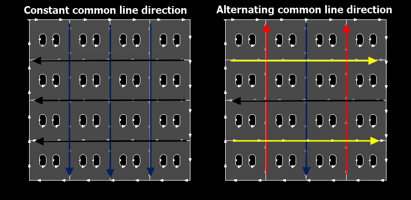
There is also a tick box with the label ‘alternate common line directions’. This gives the option for cutting each common line in alternating directions, which can reduce the rapid movement between cuts, and therefore time, required.
Common Line Alignment
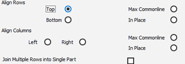
There are multiple options for how the parts are aligned when using the common line option. In addition to Max Commonline or In Place, if they are in a column they can be aligned left or right, and if they are in a row they can be aligned top or bottom. In an array, options for both rows and columns are present.
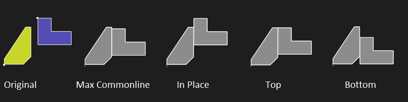
Here is an example showing the alignment options with a row selection:
Max Commonline attempts to align the parts to maximize the overlap of the common line, whereas In Place attempts to preserve the position as much as possible (some movement may be required due to the kerf offset).
In an array, there are options for aligning rows or columns. Depending on your selection, there is also an option for Join Multiple Rows into Single Part (if you are aligning by rows) or Join Multiple Columns into Single Part (if you are aligning by columns).
Cluster Pairing: S and G Cuts
Parts can be common-lined as pairs… so a single cut severs two parts. There are two variations currently supported, S and G cuts. The entire cut will be pre-offset and marked as kerf-none.
S Cuts (Best for Flame)
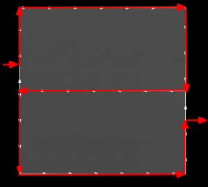
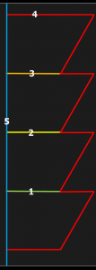
‘S’ cuts are best for flame as the path never crosses itself. Note the top part is cut clockwise while the bottom part is cut counter-clockwise; with plasma the bottom part will likely have more taper on its edges.
G Cuts (Best for Plasma)
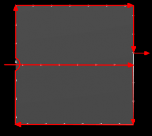
‘G-Cut’ should not be used for flame cutting as the cut may cross gaps. It is recommended for plasma cutting as it is ‘mostly clockwise’. (The exception being the common line where it is impossible to preserve the kerf side).
Common Crop
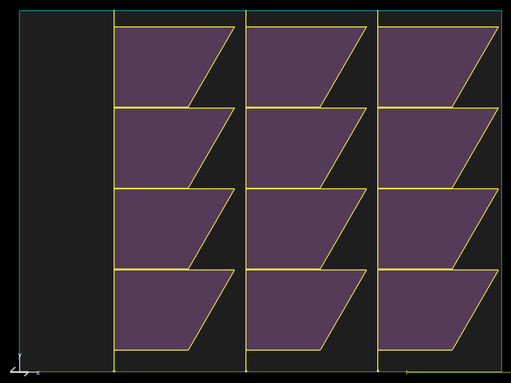
Common crop functions in a similar way common line, but also creates a crop line to sever the plate.
When a cluster is created by common cropping it, it is Forcefit as the line extends right to the edges of the plate. Because of this, it is not recommended to move the cluster after common crop as the line may miss the edges.
Common Crop Uses
This is particularly useful for plate dragger style machines where the plate (and any skeleton) is moved around in order to cut different sections as it reduces what is being moved around.
It should only be used on columns, not on rows or arrays. There should be a continuous straight line which the crop line will then extend to the edges of the plate (as in the example). Cluster pairing should not be used with common crop.
Common Crop Alignment
The common crop window provides the same alignment options as for common line, however it is usually recommended to have the crop line to the left as a normal cutting sequence would go from right to left, so the skeleton to the right can be progressively severed and removed.