PRIMECUTNE VERSION 3.5.347 RELEASE NOTES
SUPPORT FOR PASSTHROUGH MACHINES
- Ability to add “Trapdoor drops’” to drop parts from the skeleton
- Maximum nestable part width and height restrictions can be enforced
- Improved skeleton cropping- support for snaps, ortho, edge start and edge runoff (see below)
- Definable clamping areas and tool safety envelope to prevent collision of tools with clamps.
- Leadin location tendency strengthened to assist with minimizing loose part movement after cutting, ie piercing at the top left of parts on a plate is recommended as this minimises plate movement before the trapdoor drop. On internal cuts “top left” tendency is now automatically switched to “bottom-left”.
- Sequencing editor now shows completed parts (those severed from the plate as red), and tradoored parts (removed from the plate) as black during animation
The new postprocessor (machine) settings are shown below:
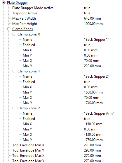
For passthrough machines, set Plate Dragger Mode Active to true. You must set Trapdoor active to true and set up a trapdoor tool to allow the trapdoor to function. Trapdoor drops are currently added manually in the sequencing editor.
- Max Part Width and Max Part Height define the maximum X and Y dimensions respectively of parts that can be nested on this machine’s plates. The restrictions are in place particularly on machines with a trapdoor but no outfeed conveyor, where all cut parts must be dropped through the trapdoor and so must fit the trapdoor and any subsequent part handling equipment.
- The Clamp Zones define hazard zones on the plate where no parts should be nested, such as wehere the grippers grip the plate. Their settings are self explanatory.
- The Tool Envelope defines how close the tools can get to a hazard or clamp, and should represent in each direction the greatest envelope requirement of all the tools. For example in the minimum Y direction the spindle may dictate how close we can nest to the clamps, due to the clamp foot geometry, while in the other directions it may be the plasma bevel envelope.
- The Trapdoor is set up as a “Trapdoor Tool,” similar to a pause tool. And also similar to pauses, trapdoor drops are manually inserted in the sequencing editor.
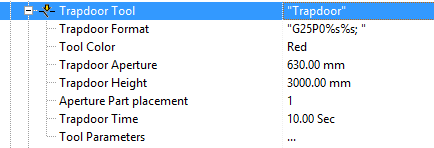
- Trapdoor Format defines how the Trapdoor command is sent to the controller. The two %s parameters are the X and Y coordinates to be sent, and how these are calculated depends on the setting of Aperture Part Placement, below.
- Trapdoor Aperture defines the X-width of the trapdoor and is used for display purposes and computing what parts are dropped when a drop occurs. Trapdoor height is the Y extent of the trapdoor.
- Aperture Part Placement determines where on the trapdoor the part is to be moved to before the trapdoor opens as follows: 0 centers the part(s) on the trapdoor, 1 places the parts at the left edge of the trapdoor (minimises plate movement before dropping, recommended) and 2 places them at the right hand edge.
- Trapdoor Time is used to allocate time for the trapdoor drop for scheduling and costing purposes.
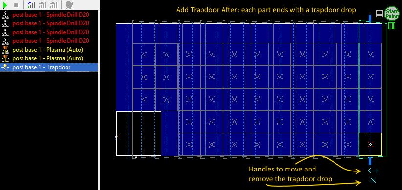
In the sequencing editor with a passthrough machine, narrow zig-zag zoned part by part sequencing with start at the right top of the plate is generally recommended:
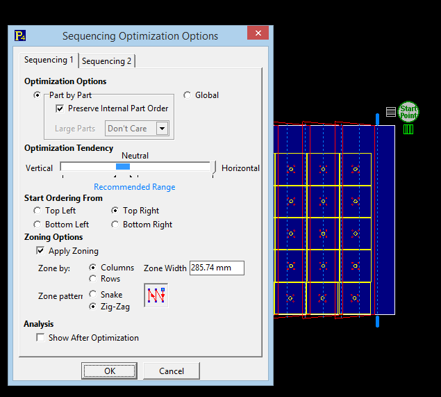
Afterwards you can select all parts, right click and choose Add Trapdoor After to drop each part immediately after it has been cut (recommended). Alternatively choose Trapdoor Selected Parts in Batches, which will cut as many parts as can be dropped in a single drop, then drop them all together- this results in faster processing with fewer drops but also involves moving loose parts around in the skeleton while cutting, increasing the risk of parts jamming.
Trapdoor drops are displayed as red trapezia, we use trapezia rather than rectangles to clarify display when there are many overlapping drops.
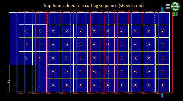
When adding trapdoors to groups, the actual trapdoor drops are added as the last item within the groups (be it a part, zone or other manually created groups). When editing a group a single trapdoor drop may be deleted by first selecting the trapdoor drop so it is highlighted, then clicking on the X handle. The drop may be moved also by dragging its translation handle but this is not recommended- it alters the parts that are dropped but not position of the drop within the sequence, thus its effects can be confusing.
There is an option to Remove All Trapdoor Drops also to clear the trapdoors. We recommend doing this after resequencing or optimising order.
You can also choose Add Trapdoor After after an indivdual cut or bevel process when editing a sequencegroup/part. This can be useful to trapdoor drop large cutouts which are unlikely to fall through the machine’s cutting aperture.
Sequence animation will now show completely cut parts (those severed from the plate but not yet trapdoor dropped) as solid red, and those parts which have been trapdoor dropped as black. “Red” parts are loose in the skeleton until they are dropped or manually removed and can cause cutting issues. If Add Trapdoor After has been applied to all parts then the animation will show the parts turning black immediately, while Trapdoor Selected in Batches will show them turning red (loose in skeleton) before several turn black at once as they are dropped.
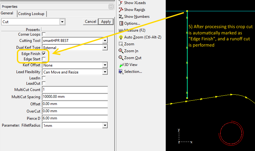
NEW POSTPROCESSOR EDGE START/STOP CONDITIONS FOR CUTTING TOOLS
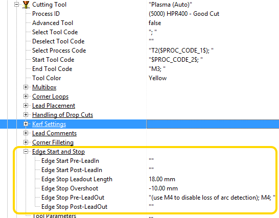
Cutting tool parameters have been grouped more logically as can be seen above. New settings have been added for special handling of cuts marked as Edge start or Edge Finish, as highlighted above. In particular:
Edge Stop Overshoot can be used to extend an edge finish past the edge of the plate (whose exact position may not be known at programming time) for remnant cropping or skeleton cropping. If given a negative value as above it will actually shorten the cut, so the above setting shortens the cut 10mm before the edge, but then an 18mm leadout is applied by the Edge Stop Leadout Length setting, resulting in effectively a 8mm overshoot. Additionally the Edge Stop Pre-Leadout code inserts an M4 command which instructs the touchcut controller to ignore loss of arc.
SKELETON CROPPING ENHANCEMENTS
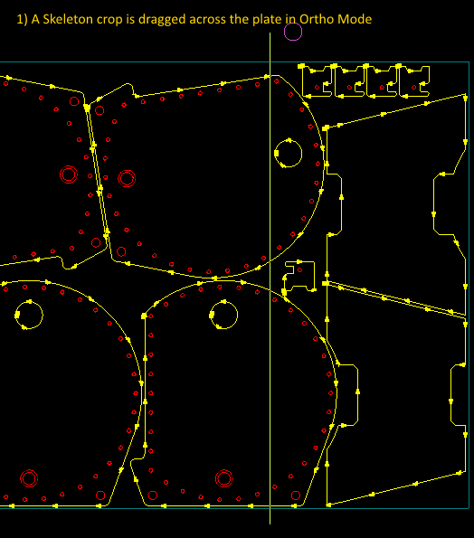
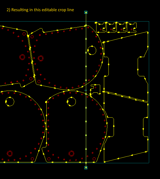
F8 (Ortho Mode) can now be enabled when shifting crop handles, to enable crops to be placed exactly parallel to plate edges. As in the geometry editor, use the SHIFT key to dynamically switch the state of Ortho mode while dragging handles.
Endpoint, centerpoint and nearest snap points have been enabled, allowing crops to snap to cutting geometry and to the plate edges.
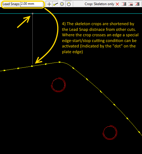
Crops can be dragged across processed parts, and they will automatically split into on-plate segments, removing the on-part sections. Additionally the Lead Snaps value is used to shorten the crops a small distance from the cuts to allow for cut kerf. A typical values for Lead Snap is thus just under twice the kerf offset/radius , ie just under the kerf diameter. This allows crop cuts to start and stop just on the edge of the cuts.
Measure mode (F2) now also uses the snaps in the processing editors, so can be more exact.
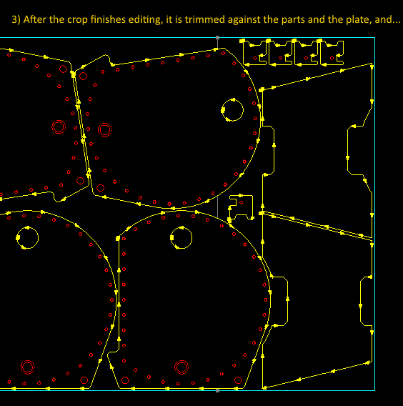
EXAMPLE SHOWING NEW PLATE CROPPING, AND EDGE FINISH CODES
The following example shows a skeleton crop being placed across a nest of parts. The end result is a series of short crop cuts. The first crop cut at the bottom can apply an edge-start on the plate edge if required, and the last cut at the top can apply a plate runoff end criterion; this latter consition is particularly useful since the plate width is often not know exactly, meaning the top edge my not be exactly where we think it is t programming time. A runoff condition is typically applied where a short distance before the nominal plate edge we pass a code to the controller telling it to ignore unexpected loss of arc, then we keep cutting a specified distance beyond the edge to ensure the plate is severed. The arc will “pop out” and the program will continue without raising an arc lost error. Note of course these runoff cuts can cause shorter consumable life.
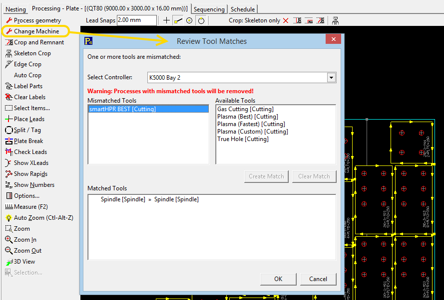
PROCESSING EDITOR CAN NOW CHANGE MACHINE
The processing editor now has a Change Machine button which remaps existing processing (on parts or plates) to a different controller, remapping tools dynamically with the Review Tool Matches dialog. Previously the part or plate would have to have been reprocessed entirely which would lose programming intent, especially on complex bevelled parts.
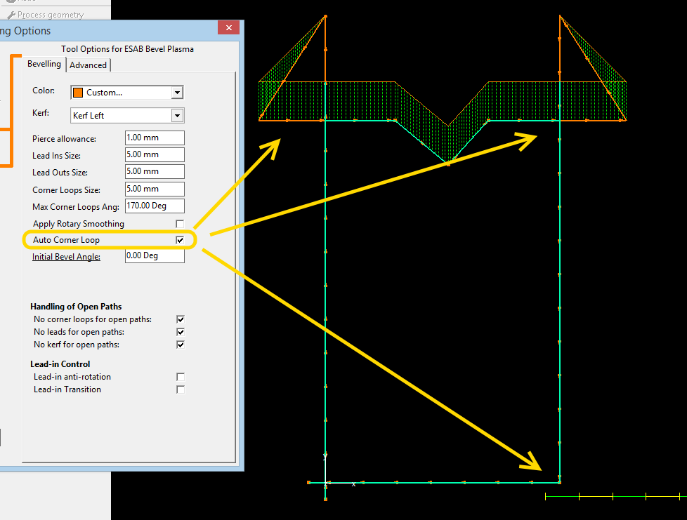
AUTOMATIC BEVEL CORNER LOOPS
When bevelling parts corner loops now appear and disappear as needed; There is a new bevel process property Auto Cornerloop (defaults to true), turn this off on the bevel process to diable this feature. Corner loops are automatically hidden if the torch is vertical both sides of the corner or if the bevel rotation changes by less than (180 degrees -bevel smoothing angle, typically 10 degrees) across the corner. There is a tool default setting for this, as some users may wish to use corner loops on all corners to maintain sharpness. This example shows corner loops being set on the top two corners where there is bevel angle and a change in bevel rotation, There is no corner loop at bottom right as the torch is vertical and is is considered unnecessary. There are no corner loops either side of the “V” at the top, as the bevel rotation has been frozen here (see below) and so rotation is not changing.
FREEZE BEVEL ROTATION, CORNER LOOP ANTIWINDUP AND SUPPORT FOR ESAB STYLE BEVELS
Postprocessor support has been added for ESAB style bevels, with rotation limits. To assist with this commands have been added to support enabling and freezing bevel rotation, and inserting “antiwindup” commands into triangular corner loops.
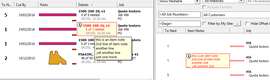
IMPROVED VISIBILITY TO NESTERS OF WORKORDER ITEM NOTES
Item notes are now shown as a column in both the item selector and in the nest explorer parts pane.
In the nest explorer parts pane the note is not shown to save screen space, but hovering over the highlight will show the item notes.
In the item selector, the ellipsis (…) at bottom left of the highlight box indicates there are more lines to the note which cannot be shown due to the size of the cell, hovering over the cell will show the full note.
In the item selector only, workorder notes are also shown in a separate column with a navy border and text, and hovering over the item in the selector shows both the item, notes and the workorder notes.
Item notes can now be set on multiple (eg all0 items of a quote or workorder at once by selecting multiple items before editing the notes. Our usual convention applies: if multiple items with differing notes are selected then the item notes tab will color itself yellow to inidicate the varying notes. Cut, copy and paste between notes using the notes tabs is now supported as well (previously the shortcut keys were consumed by the cut,copy paste item functions).